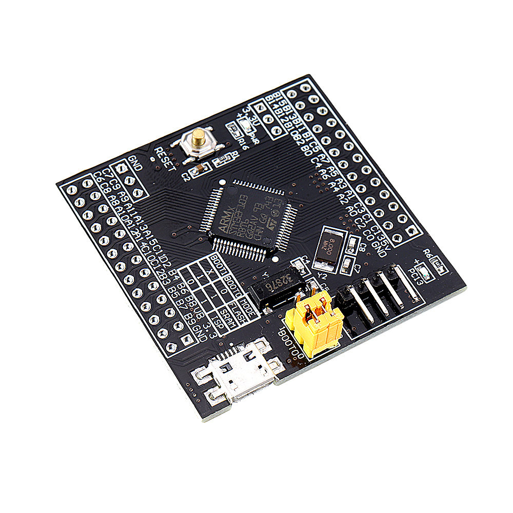
STM32F103RBT6 Core Development Board 32F103 Small System Board STM32 Development Board

Features:
1. Onboard the most basic circuit based on MCU, such as crystal oscillator circuit, USB power management circuit and USB interface.
2. Added EEPROM (I2C/1028Byte x8) storage circuit.
3. Leads to all I/O port resources.
4. With the SWD emulation debug download interface, the interface requires at least 3 wires to complete the debug download task.
5. Using the Mirco USB interface used in current smartphones, it is easy to use and can do USB communication and power supply.
6. The core crystal system (8MHz) uses the high-quality, high-quality, low-load NDK NX5032GA without the use of a low-cost iron-shell crystal.
7. Adopted the officially recommended low-load RTC crystal scheme and used the Epson brand crystal instead of the cheap cylindrical crystal.
8. The high-capacity tantalum capacitors are placed on the input and output terminals of the power supply voltage regulator chip, which will definitely have an extraordinary effect in voltage regulation and filtering.
9. It is equipped with high-quality 2*13/2.54mm pitch double-row pin to ensure excellent conductive contact, so users can place the core board on the standard universal board or breadboard. The pin header is not soldered by default, and the user can select the welding direction according to his needs.
Chip introduction:
1. Stm32F103RBT6
2. AMS1117-3.3V: 3.3V regulator chip, providing a maximum current of 1500mA.
3. AT24C08: 1024Byte x8, high data transmission rate is 400KHz and IIC bus compatible, the number of erasures is about 1 million times, and the data storage can be 100 years old.
Package Type: LQFP
Number of pins: 64
Core: CortexTM-M3
Working frequency: 72MHz
Storage resource: 128K Byte Flash, 20KByte SRAM
Interface resources: 2xSPI, 5xUSART, 2xI2C, 1xCAN, 51xI/O port
Analog to Digital Conversion: 3x ADC (12bit/16 Channel)
Timer: 3 normal timers 1 advanced timer
Debug download: support debugging download of JTAG/SWD interface, support IAP
Interface introduction:
1. SWD interface: support simulation, download and debug.
2. Mirco USB interface: Power supply and USB communication function, download is not supported.
3. USART1 interface: Can be used for USART1 to download programs, or use USART1 for communication.
4. MCU pin interface: Pull out all I/O port pins for easy connection with peripherals.
5. 5V and 3.3V power input and output interface: commonly used for external power supply, or co-processing with other modules
Other device introduction:
1. Power LED (PWR): The power indicator status determines whether the power supply is stable.
2. User LED (PC13): Facilitate I/O output test or indicate program running status.
3. Start the jump selection programming mode: (1. User Flash 2. SRAM 3. System Memory).
4. Reset button: Used to reset the chip program by the user.
5. 8M crystal oscillator: The system frequency can be set to 72MHz by multiplier setting.
6. 32.768KHz crystal: Available for built-in RTC or for calibration.
Package includes:
1 x STM32F103RBT6 Core Development Board with pins
Package includes:
1 x STM32F103RBT6 Core Development Board with pins


STM32F103RBT6 Core Development Board 32F103 Small System Board STM32 Development Board Buy Now

